Spectrum Analysis
Spectrum analysis involves the use of special RF equipment designed to listen to and analyze the frequency bands utilized by Wi-Fi devices. Because these bands are unlicensed, they are often shared with non-Wi-Fi sources of RF signals, such as wireless video cameras, microwave ovens, or cordless phones, which cause interference. The purpose of spectrum analysis is to detect and identify such sources of interference, eliminate them, and/or identify the WLAN channels with minimal interference. While spectrum analysis is not a mandatory part of a site survey, it might be very beneficial, especially in noisy RF environments.
Hardware Requirements
TamoGraph can perform spectrum analysis simultaneously with passive surveys by interfacing with one of the following USB-based spectrum analyzers:
- Wi-Spy DBx by MetaGeek, a dual-band (2.4/5 GHz) analyzer (a legacy product).
- WiPry Clarity by Oscium, a tri-band (2.4/5/6 GHz) analyzer (a legacy product).
- Wi-Spy Lucid by Oscium, a tri-band (2.4/5/6 GHz) analyzer that you can order from us, as a bundle with TamoGraph, or directly. Wi-Spy Lucid is the successor to WiPry Clarity, featuring faster scanning speeds and more accurate measurements.
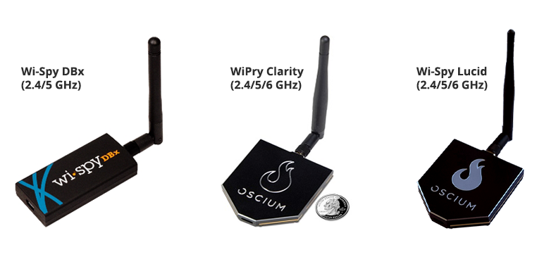
Note that you cannot use more than one WiPry Clarity or Wi-Spy Lucid devices simultaneously.
Spectrum Data Graphs
When external USB spectrum analyzer is plugged in, a live spectrum picture is displayed on the central pane of the main TamoGraph window, as shown below.
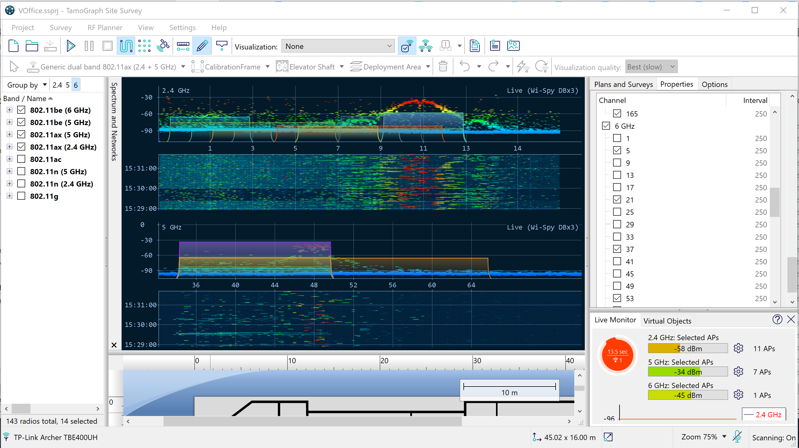
When a supported USB spectrum analyzer is connected, the spectrum pane displays live spectrum data in one or more graphs, depending on the frequency bands supported by the analyzer. The same pane displays recorded spectrum data when you point to a survey path location that contains spectrum measurements.
Right-click a graph to configure its contents and appearance. Select 2.4 GHz, 5 GHz, or 6 GHz to display one band, or select Dual to display two supported bands simultaneously. The available choices depend on the analyzer. Under Spectrum, enable Current Level to show the current signal amplitude and Max Level to show the highest observed amplitude. Use X-axis to display frequency in MHz or Wi-Fi channel numbers. You can also enable the Waterfall view to see how amplitude changes over time and allocate 1/3, 1/2, or 2/3 of the pane to the waterfall graph.
To compare spectrum activity with Wi-Fi networks, use the Networks submenu to overlay network information captured by a Wi-Fi adapter. Network outlines are positioned according to their frequency band, channel, and channel width. Select Show to display the overlay, Show SSID to add network names, Show Gradient to apply gradient fills, and Highlight Selected to emphasize networks selected in the AP list.
For a closer view of a crowded frequency range, especially in the wide 6 GHz band, turn the mouse wheel to zoom in or out. You can also drag across a range to expand it to the width of the graph. Clicking ECS while dragging cancels it. While zoomed in, hold the middle mouse button and drag to pan left or right. After placing the mouse pointer over the graph you want to control, press Up Arrow or Down Arrow to zoom and Left Arrow or Right Arrow to pan toward lower or higher frequencies. The context-menu commands Zoom → Zoom In, Zoom Out, and Reset provide the same basic view controls.
Use Reset Data to clear the data displayed in the spectrum pane. This command and the other view controls do not modify spectrum measurements stored in the project. Use Save As to save the current live spectrum view as a PNG image. Spectrum measurements collected during a survey can be included separately in PDF, HTML, or ODT reports by using Project → Generate Report.
Select Detach Window to display the spectrum pane in a separate floating window and Attach Window to return it to the main application window. To show or hide the pane, use View → Spectrum.
Only one application can control a spectrum analyzer at a time. Before viewing spectrum data in TamoGraph, close any other application that is using the analyzer.
Performing Spectrum Analysis Surveys
Spectrum data can be collected either simultaneously with passive surveys or in spectrum-only mode (you will be prompted to select one of these two options in the survey type selection dialog.) The survey procedure is very similar to the one that you follow when you perform standard passive surveys. It is described in detail in the Data Collection chapter. To collect spectrum data during a passive survey, simply plug spectrum analyzer into a USB port of your computer before you begin the survey. However, there are a few peculiarities that you should keep in mind:
- Spectrum data collection cannot be performed simultaneously with active surveys. During active surveys, spectrum data might be distorted due to the proximity of the Wi-Fi adapter that sends and receives large amounts of data. Therefore, spectrum data collection is disabled when active or simultaneous passive + active surveys are performed.
- The data collection style for a spectrum survey is typically different from the style used for standard Wi-Fi surveys. Specifically, when performing spectrum surveys, the surveyor should spend more time in each survey point before moving to the next one. However, simultaneous Wi-Fi and spectrum data collection might give the surveyor valuable information. We recommend using the point-by-point mode, as described in the Data Collection chapter, because in that mode, the spectrum analyzer has more time to collect data than it has in continuous mode. If you prefer to collect spectrum data in a traditional way, i.e., spend 30 seconds or a minute in a given location or zoom into a specific frequency range, you can do that using Chanalyzer.
Viewing Collected Spectrum Data
After you have performed a survey, the spectrum data collected can be viewed in two ways. The first option is viewing data in the main application window. When you hover the mouse over any point of the walkabout path, the spectrum pane displays the graph for the given survey point. Because a meaningful chart must contain data collected over a certain period of time (typically one minute), the chart displays data collected during the time period starting -30 seconds prior to the selected walkabout path point and ending +30 seconds following the selected walkabout path point, or a total time span of one minute. If you analyze the points at the very beginning of the walkabout path, the time span shifts accordingly. For example, for the first point, the time span would start with the first second and end with the 60th second. The same principle works for the points at the very end of the walkabout path. When you move the mouse away from the walkabout path, the spectrum pane begins displaying live data again (if compatible spectrum analyzer is plugged in.)
The second option is viewing data in PDF or HTML reports. When a report with spectrum data is generated, location markers are overlaid on the floor plan and walkabout path, and a sequence of spectrum charts corresponding to each location marker is added to the report.
Exporting Spectrum Data
The spectrum data collected during site surveys can be exported into the WSX format for subsequent viewing in Chanalyzer by MetaGeek (version 4.2.1.28 or higher required). To export spectrum data, open a project that contains a spectrum analyzer survey, select a survey on the Plans and Surveys tab, and click Project => Export Spectrum Data.