
 |
 |
| |
| Promiscuous Monitoring in Ethernet and Wi-Fi Networks |
| |
|
||||||||||
|
|
| |
Hubs are still popular devices for small networks because of their low cost, but attention should be paid to potential problems with using hubs for network monitoring. First, hubs are open to unauthorized monitoring from within the LAN segment, as any port can be used for promiscuous mode monitoring. Second, "auto-sensing", "dual-speed", "switching", or "intelligent" hubs may prevent you from monitoring the entire LAN segment. This problem will be discussed in the next chapter; meanwhile, we'll show a few alternative network layouts that use hubs for monitoring purposes. Layout 1 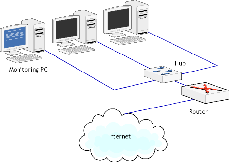
This is probably the simplest and most obvious layout. Here, any computer connected to the hub can be a monitoring computer, as the hub replicates the data received/sent to/from the router to all ports. Additionally, data exchange between the local workstations can be monitored. Layout 2 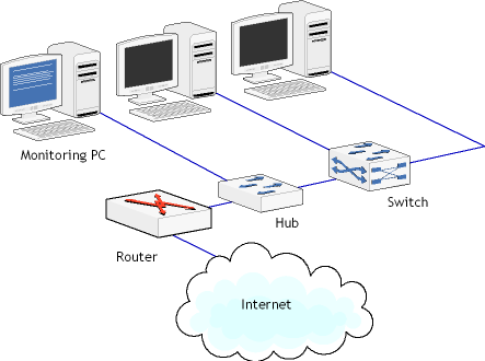
In this layout, the hub is inserted between the router and the switch. This layout allows you to monitor the data being sent to/from the Internet, but not the data being exchanged by the local workstations. Layout 3 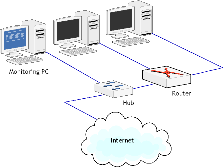
This layout illustrates how you can monitor a small LAN that doesn't use a switch. This is a typical layout for a home or small office network, where the router is combined with a switch to which a few workstations are connected. To monitor the data being sent to/from the Internet, you can insert a hub between the Internet and your router. It should be noted that the monitoring software would not be able to distinguish between traffic originating from different workstations, unless the workstations behind the router have routable IP addresses. If they don't have routable IP addresses, all packets will have the same IP address, i.e. the public IP address of your network. The monitoring computer located outside your LAN should be totally passive, i.e. the network interface should be used for data capturing only. This can be achieved by assigning a non-routable IP address to the NIC, e.g. 10.0.0.1, or unbinding TCP/IP from the NIC altogether. To achieve complete passiveness, a read-only cable can be used; this method will be discussed below. Layout 4 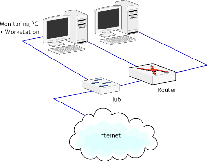
This layout is a variation of Layout 3, but here the monitoring functions are performed by one of the workstations that is equipped with two NICs: One NIC is used for normal connectivity inside the LAN, while the second NIC is used for monitoring. As with Layout 3, steps should be taken to make the second NIC passive. This layout should be considered as a budget solution only. |
|||||||||
